
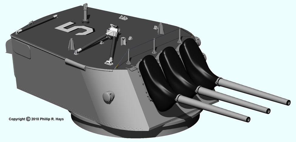
The triple 6"/47 gun turret was the Oklahoma City's primary surface battery. The turret design was developed early in the 1930s to house the new 6"/47 guns for the Brooklyn class light cruisers. It was a successful design, and was adopted for the Cleveland class in 1940. The original Cleveland class cruisers had four triple 6"/47 turrets, but only the forward #1 turret remained on the OK City after the guided missile conversions in the late 1950s. The Oklahoma City CG-5 was the last ship in the US Navy to operate the 6"/47 gun until it was decommissioned in 1979.
The turret design limited the elevation of the guns to a maximum of 41° although the gun mechanism itself could elevate to 60°. The higher elevation angle would allow the guns to be fired at high altitude aircraft targets. Some thought was given to modifying the turret for the Cleveland class to allow full elevation of the guns, but this would have delayed the introduction of the ships into the fleet. With war threatening it was decided to keep the older design.
The turret rotated 150° from the ship's center line to port and starboard at a fairly slow rate of 10° per second. The ship's superstructure was angled back from the turret to allow an unobstructed angle of fire. The guns could be loaded at an elevation range from -5° to 20°. If the guns needed to be fired at a higher elevation than 20° they were first brought to 20° and loaded, then raised to the higher angle to fire. Then they were returned to 20° to load again. This limitation, plus the relatively slow elevation rate of 11° per second and the slow train rate made the guns almost useless against aircraft targets.
Turret Structure
The turret was an armored gun house designed to protect the gun crew and guns from direct enemy fire and shrapnel and splinters from near misses. The front of the turret was 6 1/2 inch thick armor steel plate. The curved forward part of the turret sides was 3 inches thick armor plate and the remaining side plate was 1 1/2 inches thick. The rear was made of 1 1/4 inch thick armor plate. The top was 3 inches thick. The total weight of the rotating part of the turret was about 165 tons.
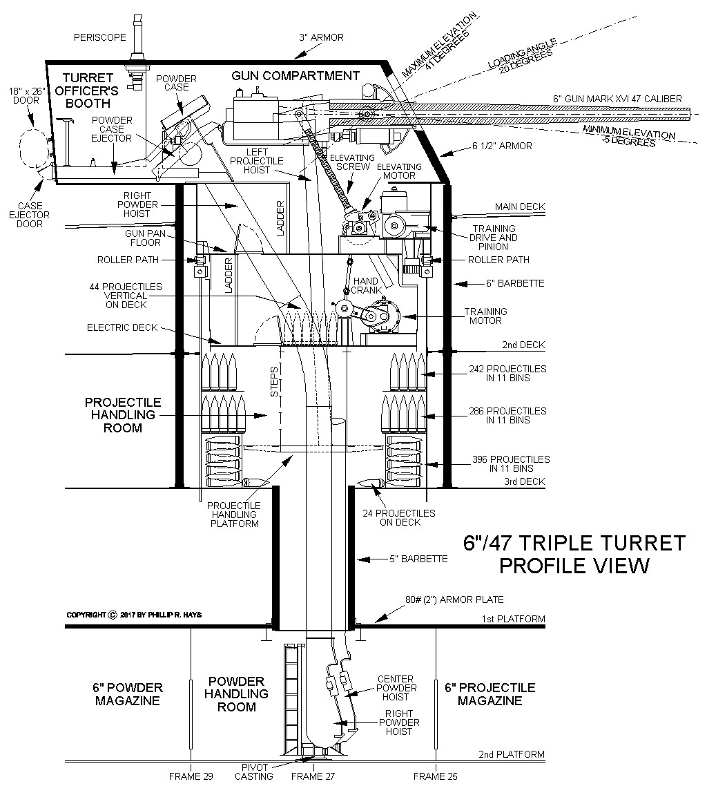
The turret was mounted in a 15 foot 4 inch outside diameter armored barbette. The 6 inch thick barbette tube extended down to the 3rd Deck. Below this a 5 foot 4 inch diameter barbette with a 5 inch thick armored tube extended down to the 1st Platform Deck. The 2 inch thick armored 1st Platform Deck protected the powder and shell magazines on the 2nd Platform Deck. The 2nd Platform was the lowest deck in the ship. Below this were fuel, water and ballast tanks and the outer hull plating of the ship.
The turret contained the Gun Compartment where the guns and the loading mechanisms were located, and the Turret Officer's Booth at the rear where the turret captain directed firing operations. A periscope allowed observation of the target. An armored door opened from the Turret Officer's Booth onto the Main Deck. The original turret design had a large optical range finder mechanism in the Turret Officer's Booth that extended from the sides of the turret, but this was never installed on the Cleveland class #4 turret and was removed later from the forward #1 turret on some ships to reduce topside weight. The Oklahoma City CL-91 and CLG-5 did not have the range finder in the #1 turret.
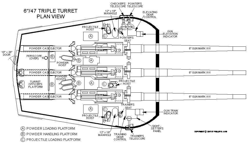
In the Gun Compartment were crewmen to operate the guns. Each gun had a gun captain, a projectile loader, a powder handler and a powder loader. The powder handlers removed the 60 pound powder cases from the Powder Hoists (left, center and right) and placed them in stowage trays behind the guns. The projectile loaders took the 105 to 130 pound projectiles from the Projectile Hoists (left, center and right) and placed them into the projectile trays on the guns. The powder loaders took powder cases from the stowage trays and placed them into the powder trays on the guns. The gun captain then operated the rammer to push the projectiles and powder cases into the gun breech and raised the breech block to close the gun.
The turret normally was operated automatically by the computers in the Surface Battery Plot Room, but it could also be operated locally from within the turret. On the left side was the Pointer operator. He could raise and lower the gun elevation as directed by the Turret Officer to bring the target into his telescope sights, and he had a trigger to fire the guns in local mode. On the right side was the Trainer operator who could rotate the turret to the bearing ordered by the Turret Officer to put the target in his telescope sights. A third Checker crewman behind the Pointer checked the aim of the guns. The Pointer, Trainer and Checker had individual telescopes projecting from the sides of the turret to allow them to observe the target to correct the bearing and elevation. The Sight Setter was on the right behind the Trainer. He adjusted the focal distance of the Pointer, Trainer and Checker's telescopes to focus on the target.
Immediately below the turret was the Gun Pan level where the gun elevating mechanism was located. A hydraulic transmission powered by a large electric motor drove the elevating gear. A large screw mechanism raised and lowered the guns. All three guns elevated together and could not be elevated independently. The training drive motor and pinion gear were also on the Gun Pan deck. The training pinion gear turned against a large fixed ring gear that circled the rotating part of the turret mechanism. The turret rotated on 84 roller bearings that traveled on the 15 foot 3 inch outside diameter Roller Path just above the training ring gear. Individual rollers could be replaced without lifting the turret. The entire weight of the rotating turret was supported by the Roller Path that was attached to the top of a 5/8 inch thick (25#) steel cylinder that extended down to the 3rd Deck. A 14 inch space between this cylinder and the inner wall of the barbette allowed inspection and maintenance.
The electric drive motor for the training system hydraulic transmission was located one deck below on the Electric Deck. A hand crank mechanism was located there to drive the train mechanism hydraulic pump. Fluid from this pump could be switched to drive the train and elevation mechanisms in case of electrical power failure or damage to the electric drive motors.
Up to 44 6" projectiles could be stored on the Electric Deck, standing vertical and lashed to chocks on the deck. But most projectiles were stored in the Projectile Handling Room. These ready service projectiles were stored in fixed bins and chocks on the deck. The Projectile Handling Platform rotated with the turret. Three Projectile Hoists carried projectiles from the Handling Platform up to the Gun Compartment. Crewmen in the Projectile Handling Room would select the type of projectiles ordered from Surface Plot and send them up the hoists. 992 projectiles could be stowed in the barbette. Additional projectiles were stowed in the 6" Projectile Magazine on the 2nd Platform deck forward of the Powder Handling Room beneath the turret.
Powder was contained in brass powder cases with cork plugs. Powder cases were stowed in containers that were stacked in bins in the 6" Powder Magazines on the 2nd Platform deck on either side and aft of the Powder Handling Room. Crewmen would carry the powder cases from the Powder Magazines to the Powder Handling Room. Three Powder Hoists (left, center and right) carried the powder cases up to the Gun Compartment.
6"/47 Mark 16 Gun
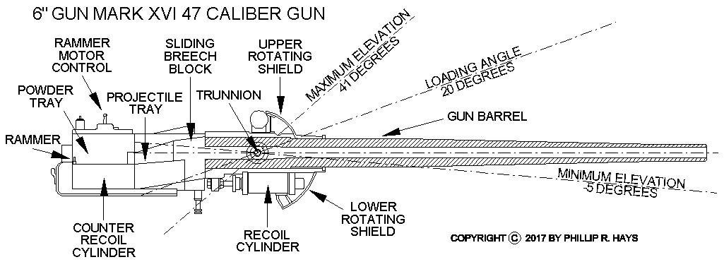
The Mk 16 6 inch (15.2 centimeters) 47 caliber gun was developed in the 1930s for use on light cruisers. It was designed to fire a new "super heavy" armor piercing round that had much greater penetrating ability than earlier armor piercing projectiles. The barrel was machined from a single radial stressed forging (monoblok) with a replaceable inner liner. The gun was designed to use semi-fixed ammunition (separate projectile and powder) and the powder was in a brass case instead of powder bags. This greatly improved safety and the rate of fire.
The caliber of US naval guns is the length of the barrel expressed as a multiple of the barrel inner diameter. Interior barrel diameter was 5.985 inches (15.2 centimeters). With the Mk 16 this meant the barrel was 5.985 x 47 or 281.3 inches (23.4 feet) long from the base of the breech block to the end. The left hand gun was a mirror image of the center and right hand guns, but they all operated the same. Each gun weighed about 31,000 pounds, and the recoiling part weighed 15,500 pounds. The barrels weighed 9,640 pounds and attached to the gun mechanisms with a rotating bayonet type fitting. The barrels could be replaced after a barrel became worn from repeated gunfire. Average barrel life was between 750 and 1050 rounds.
The gun used a semi-automatic wedge-type sliding breech block. The breech block lowered into the gun mechanism to allow the projectile and powder to be rammed into the barrel. Then the breech block rose to close the barrel. A firing pin in the breech block contacted the primer in the powder case. An electric primer fired the powder charge. If this failed a mechanical hammer could drive the firing pin into the primer to detonate the powder. Maximum pressure within the breech when the powder fired was 18.5 tons per square inch. This propelled the projectile out of the barrel at 2500 to 2665 feet per second (half a mile per second), depending upon the type of projectile. Maximum range at 41° elevation was 25,600 yards (12.7 nautical miles) with Armor Piercing projectiles and 23,000 yards (11.3 nautical miles) with High Capacity rounds. Time of flight for the Armor Piercing shell at maximum range was about 75 seconds.
When the gun fired the barrel and breech mechanism (15,500 pounds) recoiled 21 inches. A recoil mechanism in the gun absorbed the energy from the recoil piston driven by the recoiling gun. The piston drove hydraulic fluid into a reservoir and compressed air in the recoil system. Pressure from the compressed air drove the piston back to return the gun to the firing position.
Compressed air from a Gas Ejector System blew into the barrel after firing to force hot uncombusted gasses out of the barrel. This was necessary because wind could blow these gasses back into the turret when the breech was opened for the next round. There the gasses could flash into an explosion when they came in contact with oxygen in the air. This could detonate powder and projectiles being readied for the next shot. Several ships were damaged or lost from multiple navies in the early 1900s due to blow back explosions in turrets before the gas ejector systems were installed.
The normal rate of fire per gun was 8 to 10 rounds per minute.
Ammunition
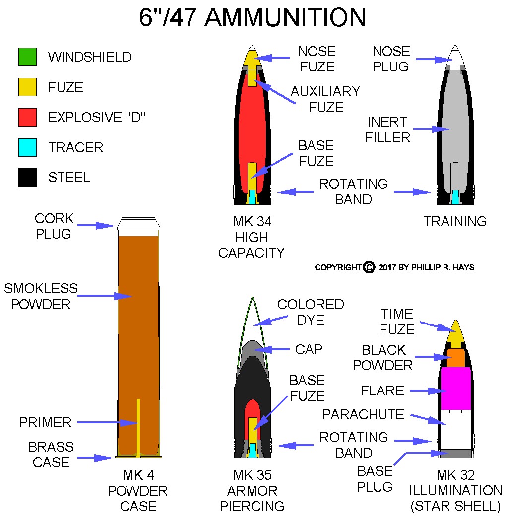
The 6"/47 gun used "semi-fixed" ammunition. The propellant powder and primer were enclosed in a brass powder case. The projectiles were handled separately from the powder case. The projectiles and powder cases were lighter and easier to handle than a combined "fixed" round with both powder and projectile in one unit. The metal powder case greatly improved safety and reduced handling time from the earlier bag type ammunition with the powder in cloth bags. The Explosive D (Ammonium Picrate) charge was less sensitive to shock than earlier charges and was safer to handle.
There were five types of projectiles for the 6"/47 gun:
- Mk 32 Mod 0 Illumination/Star Shell (ILL or SS)
- Mk 34 Mod 1 to 7 High Capacity (HC)
- Mk 35 Mod 1 to 8 Armor Piercing (AP)
- Training (BL&P)
- Training (BL&T)
The projectiles were widest at about midway along the length and again at the base. The remainder of the body was slightly smaller diameter to reduce wear on the rifling lands in the gun barrel. A soft metal rotating band near the projectile base deformed and flowed into the rifling grooves as the projectile was rammed into the barrel. It held the round in place as the gun was elevated and also produced a gas seal between the projectile body and the gun barrel. When the gun was fired and the round moved down the barrel the band rotated in the spiral rifling and friction with the projectile body imparted spin to the projectile. The centrifugal forces created by projectile rotation were necessary to arm the projectiles.
The Mk 34 High Capacity (HC) projectile was the most commonly used 6"/47 projectile. The OK City fired only 60 HC rounds at enemy targets during World War II, but fired 30,516 HC rounds in Vietnam. The ship fired no AP shells in WW II and only fired 55 Mk 35 AP rounds in Vietnam at hardened bunker targets. There is no record of the ship firing any 6"/47 Illumination rounds, although these were used by other Cleveland class ships during WW II. It did fire 44 training rounds after commissioning in 1945, and apparently none thereafter. The training rounds were inert projectiles. The BL&P (Blind Loaded and Plugged) rounds did not have a tracer. The BL&T (Blind Loaded and Tracer) rounds contained a tracer.
The Mk 32 Illumination round was 23 inches long and weighed 94.5 pounds. It was used to illuminate targets at night. It contained a Mk 4 parachute and flare. The bottom of the projectile was a loosely fitted base plug that could be forced out of the projectile. A Mechanical Time Fuze was set before firing to activate the flare at the desired distance and altitude. When the fuze went off it detonated a 3.5 ounce charge of black powder that pushed the flare, parachute and bottom plug out of the projectile and ignited the flare. The parachute had a retaining wire that prevented it from opening immediately because of the high velocity of the projectile. After the flare had burned a few seconds, allowing the assembly to slow down due to air drag, the retaining wire burned away allowing the parachute to open fully. The flare then descended under the parachute at 350 feet per minute over the target. The magnesium flare burned for 8 minutes, producing a 300,000 candlepower white light.
The Mk 35 Armor Piercing (AP) round was 27 inches long, weighed 130 pounds, and contained 1.95 pounds of explosive D. The projectile was designed to penetrate up to 6 inch thick armor plate. It used a Mk 21 Base Fuze that fired 0.035 seconds after impact with armor plate or on impact into water. The projectile had a 17 inch long blunt body of forged and tempered alloy steel, with an additional cap of tempered alloy steel soldered to the body. The blunt point of the body increased the angle at which the round would pierce armor without ricocheting. The projectile had a long windshield of thin metal to place the center of gravity near the center of the aerodynamic shape. The windshield increased the range of the projectile by reducing air drag. When the projectile impacted armor plate the cap deformed, providing the initial stress to the plating. The cap then spread out around the main armor piercing body which penetrated into the armor. After sufficient time to penetrate the armor the base fuse detonated the explosive charge to further deform the armor plate and scatter shrapnel and fire inside the target. The AP projectile could carry an optional powdered dye inside the windshield. Upon impact the dye was ejected to allow spotting the fall of the shot - different ships could use different color dyes so they could distinguish their own fire from other ship's fire. The AP round could carry a Mk 5 tracer or the tracer hole could be plugged. The tracer created a bright orange light that allowed observation of the projectile's path.
The Mk 34 High Capacity (HC) round was 27 inches long, weighed 105 pounds and had 13.22 pounds of explosive D. The blast from the explosive charge was its primary effect, with some shrapnel from the fragmenting steel case. It used a Mk 28 Base Fuze that detonated with no delay after impact with 1/4 inch metal plate or water. The HC projectile could also have a steel nose plug or a nose fuze. The nose fuzes could cause the projectile to explode under a variety of conditions other than impact with a target. An Auxilliary Fuze behind the nose fuze served as a booster for the nose fuze. The HC round could carry a Mk 5 orange tracer or the tracer hole could be plugged.
The Mk 29 Point Detonating Fuze (nose fuze) would detonate the charge with no delay upon contact with thin metal plate or after contacting water at greater than an 8° angle. It had a mechanical safing switch that had to be rotated to the arm position before the round was placed into the gun.
The Mk 63 Mechanical Time Fuze (nose fuze) had a clockwork mechanism to detonate the projectile after a preset time delay. The time delay was calculated by the Mk 8 Rangekeeper in Surface Plot and the fuze time was set just before the projectile was loaded into the gun. It could be set to detonate the projectile above ground targets to spray shrapnel over the target area.
The Mk 47 Variable Time Fuze (VT nose fuze) broadcast a radio signal and was triggered when the signal was reflected back from a target. This made it far more effective against aircraft than the Mechanical Time Fuzes. VT fuzes required no pre-fire settings. They incorporated wet electrolyte batteries to power the tiny electron tube circuit that produced and detected the radio signal. The electrolyte was in a glass ampoule that was broken by the acceleration (setback) during firing. When the fluid soaked into the battery it generated electricity that charged a firing capacitor. A centrifugal switch prevented the capacitor charge from reaching the firing circuit until centrifugal forces opened the switch. In addition, a mechanical delay timer prevented arming of the fuze until 0.4 second after firing. Several other safety features required setback and centrifugal forces to arm the fuze. The transmitting circuit projected a conical radio signal in front of the projectile. This prevented triggering by nearby objects that would be out of the path of the exploding projectile fragments. When a reflected signal was detected the circuit discharged the firing capacitor to detonate the projectile. The VT fuze could be used against aircraft or against ground targets where an aerial burst 10-30 feet above the ground would scatter shrapnel over an area.
The Mk 17, Mk 44, Mk 46 and Mk 54 Auxilliary Fuzes worked only with a nose fuze in the HC projectile, acting as a booster for the nose fuze. The Mk 44 worked only with the Mk 47 Variable Time Fuze. The nose fuze charge didn't generate enough shock to detonate the Explosive D charge. The auxiliary fuze boosted the nose fuze to detonate the charge.
Fuzes contained several safety features to prevent accidental detonation if they were dropped. They were armed either by the acceleration in the gun barrel, or centrifugal force from rotation imparted on the projectile by the rifling in the gun barrel, or both.
Powder
The Mk 4 Powder Case was 38.2 inches long, with a 2 inch cork plug, and was 7.85 inches diameter at the base flange. It used a Mk 13 combination primer. The primer could be detonated electrically or by a blow from a firing pin in the breech of the gun. The case was made of brass and weighed 28.2 pounds empty, with 32 pounds of propellant, for a total weight of 60.2 pounds. It produced a muzzle velocity of 2500 feet per second with the AP round, 2665 feet per second with the HC projectile and 2700 feet per second with the Illumination round. The powder could be:
- SPD smokeless powder stabilized with diphenylamine.
- SPDN smokeless powder with additional non-volatile stabilizers.
- SPCG flashless smokeless double-base powder with nitroglycerine and carbamite stabilizer.
- SPDF flashless smokeless powder.
A Mk 4 Reduced Charge version was also produced that contained 21 to 22 pounds of SPDN or SPDF powder in the same case as the full charge case. It produced a 2225 feet per second muzzle velocity with the HC projectile.
A 25 inch long Mk 4 Short Case version was manufactured. It was used to eject projectiles from a gun after a misfire, when the faulty powder case had been removed from the gun.
References
1. NAVSEA OP 1664, United States Explosive Ordnance, Volume 1, Navy Department Bureau of Ordnance, 28 May 1947.
2. OP 2215 Navy Gun-Type Ammunition, Department of the Navy Bureau of Ordnance, 19 January 1959.