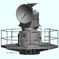
The Talos missile was a "beam rider" - it followed a guidance beam to its target. The SPW-2 guidance radar was the data link between the Missile Fire Control System Mk 111 computer and the missile. It's C-band transmitter generated the guidance beam that steered the missile to the target. The SPW-2 operated independently from the SPG-49 tracking radar, allowing the missile to be guided to an intercept point ahead of the target being tracked.
Two AN/SPW-2 guidance antennas were located on the after superstructure near the AN/SPG-49 target tracking radars. The transmitters, receivers and control electronics were located in the SPW-2 control room in the after superstructure. Each AN/SPW-2 antenna carried a platform where a Mk 12 closed circuit television camera with a Mk 5 lens could be mounted. This camera could be used to track the missile at short ranges and to view calibration targets for system alignment. The antenna mount also carried an optical telescope that was used for platform alignment.
The signal from the SPW-2 was detected and decoded by the missile. Then the missile transmitted a tracking signal that was detected by the SPW-2 and sent to the Mk 111 Missile Fire Control Computer to provide missile bearing, elevation and range data during cruise to target. The Mk 111 computer steered the AN/SPW-2 antenna beam to guide the missile to intercept the target. The missile maneuvered to stay near the center of the guidance beam. When the missile neared the target commands in the SPW-2 guidance beam switched the missile to homing mode to intercept the target.
Missiles were launched into the AN/SPW-2 guidance beam. While the booster burned the missile did not maneuver so it could wander away from the center of the guidance beam. During the boost phase a wide capture cone was broadcast. After the missile separated from the booster an antenna at the rear of the missile detected the guidance signal and the missile electronics steered the missile to the beam axis of rotation. Then the cone was narrowed to provide the guidance beam to direct the missile to the intercept point. The missile continued to ride the beam until the final moments before intercept.
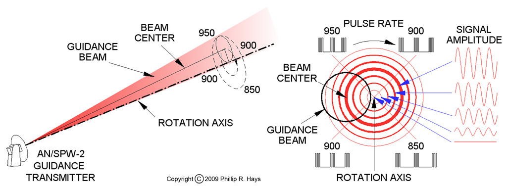
The AN/SPW-2 beam was rotated around the rotation axis (boresight axis) with the beam at an angle to the axis. The beam offset has been reported to be 0.85° from the rotation axis with a 3.5° beam width or an offset of 2° from the axis with a 4° wide beam. The beam swept a conical area around the rotation axis as it rotated, slightly overlapping the rotation axis. The beam was narrower close to the antenna and wider at a distance.

Each ship's SPW-2 guidance transmitter generated a signal that consisted of groups of three pulses at short intervals followed by a relatively long period with no pulses. The pulses carried a code to identify the particular AN/SPW-2, allowing the missile to identify the correct guidance beam if it crossed multiple guidance beams. The correct code was programmed into the missile while on the launcher just before firing.
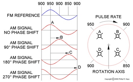
The pulse group repetition rate was not constant, but was varied according to the position around the conical scan. The beam rotated to sweep around the conical scan 30 times per second, clockwise with respect to the direction from the ship to the missile. The pulse rate was changed from 850 pulse groups per second to 950 and back to 850 each time the beam circled around the rotation axis. This produced a 30 Hz sinusoidal frequency modulated (FM) signal that was the timing reference for the beam rider guidance system. This told the missile where the beam was with respect to the rotation axis - where the missile should be.

If the missile was flying along the rotation axis the amplitude of the guidance signal was constant. This told the missile that it was on course. If the missile strayed off the flight path the signal intensity would not be constant, but increased out to the center of the guidance beam and then fell off father out. When the beam swept around to the side of the rotation axis where the missile was flying the signal strength peaked, and when it rotated to the opposite side of the axis the signal strength decreased to a minimum. The missile detected a signal that alternately increased and decreased in amplitude at the 30 Hz beam rotation frequency. The timing of this amplitude modulated (AM) signal relative to the FM reference signal was dependent upon the position of the missile relative to the guidance beam rotation axis.
The missile compared the timing of the peaks of the AM signal (missile position) with that of the FM signal (beam position) to determine the phase relationship (where the missile was relative to where it should be). The phase relationship between the two signals determined which way the missile should steer to get back to the beam axis. For example, if the guidance beam AM signal strength peaked when the FM frequency was 950 pulse groups per second (position A in the diagram, no phase shift), the missile was flying high to the left of the beam axis. If the AM signal strength peaked at 850 pulse groups per second (position C, 180° phase shift) the missile was low to the right. The output of the phase detector was fed to circuits that derived the correct combination of wing motions to steer the missile to the beam axis.
To change the course and intercept point for the missile the missile fire control computer moved the guidance beam and the missile would detect its position off center and steer to follow the beam. In flight the missile did not actually fly a perfectly straight line along the beam, but wobbled or spiraled from side to side as it flew in and out around the rotation axis.
References
1. Talos Guidance System, Joseph Gulick, W. Coleman Hyatt and Oscar M. Martin, Jr., Johns Hopkins APL Technical Digest, Volume 3, Number 2, 1982, page 142.
2. The Talos Ship System, Elmer D. Robinson, Johns Hopkins APL Technical Digest, Volume 3, Number 2, 1982, page 162.
